| Reference: | P-24-U:2002-222, LA-UR-04-1475 |
|---|---|
| From: | Damian Swift, P-24 |
| To: | Distribution |
| Date: | 18 Sep 02 |

Primary objectives:
Opportunistic:
| TRIDENT schedule | |||
|---|---|---|---|
| Plan | Actual | Comments | |
| Start of TXD set-up | 22 Aug | 26 Aug | Simultaneous short-pulse development |
| Start of facility time | 26 Aug | 26 Aug | |
| First timing shot | 26 Aug | 27 Aug | very late in day |
| First TXD shot | 28 Aug | 29 Aug | |
| Last shot | 5 Sep | 5 Sep | |
| End of facility time | 6 Sep | 5 Sep | |
| Shot allocations | |||
|---|---|---|---|
| Plan | Actual | Comments | |
| Timing etc | ~10 | 8 | |
| Intensifier trial | 0 | 0 | combined with timing and data shots |
| Polycrystal TXD | 5-10 | 8 | |
| Image plate trial | ~5 | 3 | 3 additional shots combined with data shots |
| Close-in TXD source | ~5 | 1 | |
| VISAR | 10-20 | 11 | |
| Total | 40-50 | 31 | |
| Firing duration and rate | |||
|---|---|---|---|
| Plan | Actual | Comments | |
| Experiment time | 6.0 | 3.5 | Unanticipated delays and down-time. |
| Shots/day | 7.0 | 6.6 | |
| Si (100) with Al coating | MST-7 |
| Sn foil | Goodfellow Inc |
| Be foil | Research Metals Inc and Goodfellow Inc (thicker piece) |
| Al foil | MST-7 and TRIDENT X-ray filter stock |
| Ti, V, Mn backlighters | MST-7 |
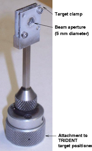
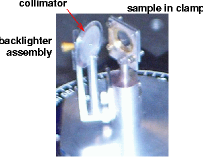
For all TXD shots other than with a close-in backlighter, the re-usable TXD holder developed for the Aug 2001 TXD series was used. This holder incorporated a detachable collimator for polycrystal diffraction experiments. The collimator was an aluminium disc 5/8" in diameter and 1 mm thick, with a 1 mm diameter hole; it was rotated in the holder to alter the spot size on the sample. The backlighter was the standard TRIDENT design of a metal foil in a gold cone; this was press-fitted into the holder and secured with "Tacky Wax" to reduce the risk of losing the cone during handling.
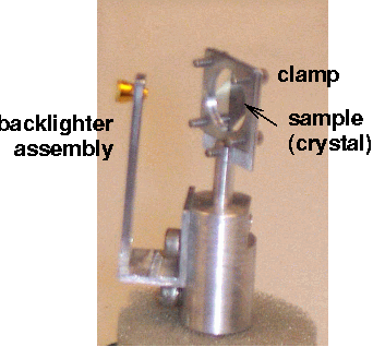
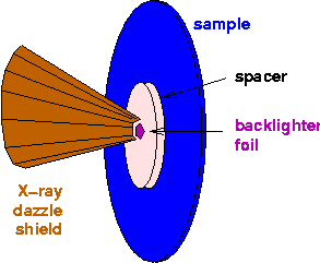
For the TXD shots with a close-in backlighter, the design attempted was to attach the backlighter directly to the sample with a spacer made of CH-based plastic. A spacer disc of plastic was glued by its edges to the sample, and the backlighter foil was glued to the spacer. A shield to protect the X-ray diagnostics from direct shine was constructed from copper sheet (obtained from the Black Hole, Los Alamos) bent to form ~half of a truncated cone. The target assembly was attached to then VISAR clamp using pieces of "Tacky Wax". This concept was inspired by a design used by Dan Kalantar at OMEGA.
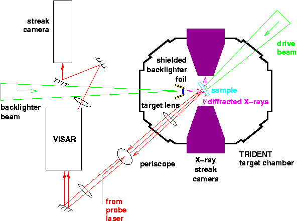
X-rays from the plasma were incident on the sample material, and diffracted according to the Bragg condition. For single crystal samples, a large part of the sample was illuminated and the Bragg return occured from a circular arc in the surface. For polycrystal samples, the X-ray source was collimated through a hole in a thick Al disc so that a small spot was illuminated on the surface of the sample; only crystallites oriented in the appropriate direction contributed to Bragg reflections.
Diffracted X-rays were recorded on Kentech X-ray streak cameras situated to the north and south sides of the target; the slit of each camera was horizontal. The sweep period of the Kentechs was set to 2 ns throughout, and the backlighter operated 3.69 ns after the drive beam. The image from the Kentech intensifiers was recorded on optical film. Static film packs (DEF film) were mounted in front of the slit in each camera. In some shots, a static image plate was placed vertically in front of one or other of the cameras.
The X-ray detectors were shielded from direct shine from the source by an attenuating layer. This was the standard Au truncated cone around the backlighter foil, except in the close-in trials where a section of a truncated cone of Cu (thicker than the Au) was used.
The X-ray source was monitored with a spectrometer mounted with the "Tubby" film detector.
| sweep speed | delay |
|---|---|
| (ns) | (ns) |
| 50 | 2390 |
| 20 | 2430 |
| 10 | 2441 |
| 5 | 2451 |
| camera from laser | 449 |
| Shot | Target | Backlighter | Line VISAR | Laser drive | Comments | |||
|---|---|---|---|---|---|---|---|---|
| sweep | delay | duration | loading energy | backlighting energy | ||||
| (ns) | (J) | (J) | ||||||
| 27 Aug | ||||||||
| 14988 | - | - | - | - | - | - | - | A/B timing |
| 28 Aug | ||||||||
| 14989 | - | - | - | - | - | - | - | A/B timing |
| 14991 | - | Au disc | - | - | - | - | - | X-ray streak timing |
| 14992 | - | Au disc | - | - | - | - | - | X-ray streak timing |
| 14993 | - | Au disc | - | - | - | - | - | X-ray streak timing |
| 14994 | - | Au disc | - | - | - | - | - | X-ray streak timing |
| 14995 | - | Au disc | - | - | - | - | - | X-ray streak timing |
| 14996 | Al, 29 µm / LiF | - | 50 | 2395 | 2.5 | 9 (IR: 30) | - | fringes weak and close together but some motion; no drive history |
| 14997 | Al, 29 µm / LiF | - | 20 | 2438 | 2.5 | 10 (IR: 34) | - | low VISAR signal; nice ramp drive |
| 14998 | Si (100), 30 µm / Al | - | 20 | 2438 | 2.5 | ? (IR: 9) | - | very low VISAR signal; low intensity ramp and reverberation |
| 29 Aug | ||||||||
| 15000 | Be foil, ~25 µm | Ti | - | - | 1.0 | - | 145 | collimator flat on; thick band on S camera, nothing on N |
| 15001 | Si (100), 30 µm / Al | - | 20 | 2438 | 2.5 | 11 (IR: 34) | - | good ramp drive and VISAR record |
| 15002 | Be foil, 55 µm | Ti | - | - | 1.0 | 50 | 209 | collimator twisted; apparently clear double-line structure plus extra fatter line on S camera |
| 3 Sep | ||||||||
| 15004 | Be foil, ~25 µm | Ti | - | - | 1.0 | - | 179 | image plate at N side; surface damaged by fringes of A beam |
| 15005 | Si (100), 30 µm / Al | - | 20 | 2438 | 2.5 | 36 (IR: 88) | - | lumpy drive pulse; shock structures in VISAR data |
| 15007 | Si (100), 30 µm / Al | Mn | - | - | 1.0 | - | 206 | close-in design; image plate with 25 µm CH2 shield; plate surface still damaged |
| 15008 | Si (100), 30 µm / Al | - | 20 | 2438 | 2.5 | 21 (IR: 53) | - | good ramp drive and VISAR record |
| 15009 | Be foil, 55 µm | Ti | - | - | 1.0 | 49 | 208 | S streak: apparently unshocked and shocked lines |
| 15010 | Be foil, 55 µm | - | 20 | 2438 | 2.5 | 21 (IR: 53) | - | VISAR signal very low |
| 4 Sep | ||||||||
| 15012 | Be foil, 55 µm | Ti | - | - | 1.0 | 103 | 198 | S streak: apparently unshocked and shocked lines; deviation varied with time |
| 15013 | Al foil, 29 µm | - | 20 | 2438 | 2.5 | 24 | - | VISAR signal very low |
| 15014 | Be foil, 55 µm | Ti | - | - | 1.0 | 115 | 168 | |
| 15015 | Si (100), 30 µm / Al | - | 20 | 2438 | 2.5 | 27 | - | low VISAR signal, but ramp wave evident |
| 15016 | Si (100), 30 µm / Al | Mn | - | - | 1.0 | - | 205 | Bragg signal apparent |
| 5 Sep | ||||||||
| 15018 | Si (100), 30 and 59 µm | - | 20 | 2438 | 2.5 | 33 | - | Clear isentropic waves. |
| 15019 | Si (100), 380 µm | Mn | - | - | 1.0 | - | 182 | Image plate shielded with 12.5 µm Al and CH2; no PCD record |
| 15020 | Si (100), 30 and 59 µm | - | 20 | 2438 | 2.5 | 62 | - | VISAR signal low, but clear isentropic waves. |
| 15021 | Al foil, 29 µm | Ti | - | - | 1.0 | - | 198 | Image plate to N, shielded with 12.5 µm Al and CH2. |
| 15022 | Si (100), 30 and 59 µm | - | 20 | 2438 | 2.5 | 13 | - | Clear isentropic waves. |
| 15023 | Al foil, 29 µm | Ti | - | - | 1.0 | - | 197 | Image plate to N, shielded with 26 µm Al. |
| 15024 | Be foil, 55 µm | Ti | - | - | 1.0 | 222 | 209 | Image plate to S, shielded with 26 µm Al.; local damage from foil debris. |
| Shot | N streak | N time-integrated | S streak | S time-integrated | Source spectrum | Comments |
|---|---|---|---|---|---|---|
| 15000 | - | n/a | broad, faint line(s) | n/a | Tubby problem | |
| 15002 | - | ?lines at edges | strong line(s) | broad, curved line | Tubby problem | |
| 15004 | - | - | ?lines/mess against dark background | broad, curved line | n/a | |
| 15007 | - | - | complicated structures | overexposed | Tubby problem | |
| 15009 | - | - | lines: 1 strong + 1 weak | weak, broad, curved line | OK Ti | |
| 15012 | - | ?line at edge | broad bending lines: 1 strong + 1 medium | medium, broad, curved line | OK Ti | |
| 15014 | - | ?lines at edges | broad bending lines: 1 strong + 1 medium | ~smooth background | OK Ti | |
| 15016 | - | - | very broad lines + structured noise | weak line + structured blob | no signal at all | |
| 15021 | n/a | n/a | broad line + noise | n/a | OK Ti | |
| 15023 | - | - | very broad lines + structured noise | - | no signal at all | |
| 15024 | - | - | broad bending lines: 1 strong + 1 weak | high background + light spot | OK Ti |
The new intensifier worked without problems on the south Kentech, and seemed to be a considerable improvement over the old intensifiers.
Using a collimated beam from a Ti backlighter, diffraction signals were apparently detected on the static film, X-ray streak record and possibly the image plates, from Be foils. This is a confirmation of the results obtained previously. Also apparently, the polycrystal TXD signal was intense enough to be observed when the collimated beam was narrow enough to allow the doublet backlighter wavelengths to be distinguished. The experiments were repeated with a shock wave in the sample; a pair of lines was observed, with variations of deviation in time and with different drive intensities. The records require further analysis to allow a clearer interpretation, because there were some unexpected systematic features about them.
Experiments were also performed with an Al foil sample and a Ti backlighter; analysis of the image plate records is to determine whether any signal was obtained.
Sample image plates were obtained, used in TXD shots, and scanned to reveal varying degrees of exposure and possibly diffraction lines. Schemes were investigated to shield the plates from damage, and also to attenuate the X-ray intensity. Where closest to the experiment (~5 to 10 mm), the image plates were always saturated. We did not optimise X-ray filtering to best bring out the TXD lines. (Apparently, image plates have an effective dynamic range of 105 to 106, and it is often possible to extract quantitative data from saturated images by repeated scanning - up to 20 times. We scanned some of the plates three times; analysis will be reported separately.)
We had hoped to perform trials with the image plates cut into pieces and folded or bent so that a large solid angle could be monitored around a TXD experiment. We spent a significant amount of time developing methods to shield the surface of the image plate from stray but intense laser light from the "A" or "B" beams, deposited material from the plasma, and fragments from the sample or backlighter assembly. We were offered the use of two scanners: one in DX-div which was capable of scanning oddly-shaped pieces but required a Q-cleared person for access, and one in P-22 which we were able to borrow for the last couple of days of the experiments but which was restricted to letter-sized image plates with no creases. For these reasons, the only image plate data obtained were from complete letter-sized plates; there seems to be no reason why target-enveloping detectors based on image plates could not be developed in a fairly short time. The work required would be the optimisation of X-ray filters and the design of a suitable holder, including a scheme to align the target.
A range of designs was considered, two prototype targets were assembled, and one was fired. It is not yet clear whether diffraction was obtained, but useful experience was obtained for future experiments. No further experiments were performed because there was insufficient time for improved targets to be assembled. Furthermore, the amount of shot time available was less than originally requested; something had to be cut back and it was this.
Secondary objectives:
Further line VISAR records were obtained in Si crystals and Al foils, with sweep periods down to 20 ns. The clarity of the data was relatively poor for the Al foils, and no usable fringes were obtained from the relatively diffuse Sn foils - so none of these were fired. It is likely that fringes would have been obtained more easily in a dedicated series of experiments with time to adjust the VISAR alignment more carefully, but this was not appropriate for experiments slipped in between TXD shots where convenient.
The highlight of the VISAR experiments was the opportunity to evaluate different loading paths. Gentle ramp waves were produced very successfully by the TRIDENT staff. At 2.5 ns long, these proved eminently suitable to generate quasi-isentropic compression histories in Si and Al samples up to over 60 µm thick at pressures up to at least ~10 GPa, with a small fraction of the laser energy available. Example experiments were performed with two thicknesses of Si fired side-by-side, which should provide usable isentropic compression data.
There seems to be no reason why TRIDENT could not be used to simulate a Taylor wave or the release behind a von Neumann spike, as I have suggested previously. This was not attempted in the present series of experiments because of a lack of time: shock and release experiments of this nature need to be planned carefully to avoid undesired spall.
| Ron Perea | Provision of backlighter assemblies, plastic sheet and metal foils |
| Randy Simpson | Laser/optics consulting, VISAR alignment, TLC for probe laser |
| Tom Hurry, Nathan Okamoto, Fred Archuleta, Ray Gonzales | target area and laser work |
| Tom Sedillo | Help with setting up the Kentech cameras |
| Ben Stillwell | Image plates, scanning, advice on use of image plates |
| Russ Olson | Loan of image plate scanner, advice on use of plates |
| Terry Langham | Liaison with Ben Stillwell for reading image plates using scanner in DX-div. |
| Allan Hauer | Project support (use of TRIDENT) - C10: HEDP |
| Cris Barnes | cbarnes@lanl.gov
|
| Steve Batha | sbatha@lanl.gov
|
| Juan Fernández | juanc@lanl.gov
|
| Robert Gibson | rbg@lanl.gov
|
| Allan Hauer | hauer@lanl.gov
|
| Randy Johnson | rpjohnson@lanl.gov
|
| George Kyrala | kyrala@lanl.gov
|
| Carter Munson | cmunson@lanl.gov
|
| Dennis Paisley | paisley@lanl.gov
|
| Mike Sorem | msorem@lanl.gov
|
| Damian Swift | dswift@lanl.gov
|
| External: | |
|---|---|
| LLNL (Dan Kalantar) | |
| Oxford U (Justin Wark, Jim Hawreliak) | |
