| Reference: | P-24-U:2003-051, LA-UR-04-1508 |
|---|---|
| From: | Damian Swift (P-24), Scott Greenfield and Aaron Koskelo (C-ADI) |
| To: | Distribution |
| Date: | 29 February, 2004 |

Primary objectives:
Opportunistic:
Success ratings are based on what we expected to achieve during the session, not on all that could possibly be done.
| TRIDENT schedule | |||
|---|---|---|---|
| Plan | Actual | Comments | |
| Start of access and set-up | 16 May | 16 May | preparatory work done during Be melt campaign from 5 May |
| Start of facility time | 19 May | 27 May | alignment beams etc from 19 May |
| First shot | 19 May | 27 May | |
| Last shot | 22 May | 30 May | |
| End of facility time | 23 May | 30 May | |
| Shot allocations | |||
|---|---|---|---|
| Plan | Actual | Comments | |
| Setup | ~6-10 | - | Actual: counted among data shots below. |
| NiAl single crystals | ~8-12 | 3 | Obtained all desired data. |
| NiAl bicrystals | 2 | 6 | Additional samples delivered from ASU. |
| Si crystals | (setup) | 13 | |
| Cu | (setup) | 1 | |
| RuAl | 0 | 2 | Scoping shots. |
| Total | ~20 | 25 | |
| Firing duration and rate | |||
|---|---|---|---|
| Expected | Actual | Comments | |
| Experiment time | 4.0 | 4.0 | |
| Shots/day | 8.0 | 6.25 | Preshot setup was generally more involved than expected. |
| Si (100) with Al coating | MST-7 |
| Si (100) and (111) uncoated | Goodfellow Corp |
| Cu foil | Goodfellow Corp |
| NiAl crystals | Ken McClellan, John Brooks, and Darren Byler, MST-8 |
| NiAl bicrystals | Pedro Peralta and staff, Arizona State University |
| RuAl | Ken McClellan, John Brooks, and Darren Byler, MST-8 |
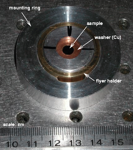
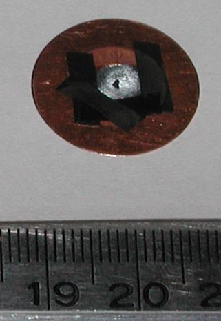
Samples were typically 5-8 mm in size, and the flyer holder was not suitable to hold them in place directly. Washers were punched from 250 µm Cu foil, the outer diameter being a close fit within the flyer holder and the inner diameter roughly 5 mm. Samples were fastened across the hole using thin strips of insulating tape to hold their edges, and an additional washer punched out of Cu or plastic shim stock if it was felt necessary. The sample/washer assembly was then held against one face of the flyer holder by packing the holder with plastic rings.
The flyer holder obscured the view from the east alignment telescope, which is the usual way of checking alignment before a direct drive shot. Alignment was set approximately before the first shot of the day by replacing the target holder with a 2" diameter disc with a hole a couple of mm diameter in the center. This was not quite representative of real samples, and the center of the drive was sometimes appreciably off-center in terms of shock arrival (slight lag at one edge) and surface displacement (off-center dome shape).
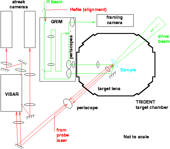
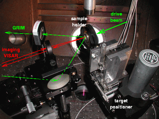
The optical layout used was based on the standard VISAR layout, adjusted slightly to allow GRIM access through the west port. There was some conflict in setting up the diagnostics before each shot, as the adjustments required for the GRIM necessitated blocking the VISAR beams for a while.
The camera slits were set to 300 µm.
The timing offsets for the west streak camera had been established accurately by Tom Tierney for the preceding Be melt series, following the previous procedure of passing an element of the drive pulse through the VISAR optics to the camera, and adjusting until the element appeared close to the center of the camera. The east streak camera was brought up during the experiments, and there was no opportunity to time it in using the same procedure. The delay was established approximately by detecting the peak in the probe laser pulse, and then refined for the 50 ns sweep period by adjusting it slightly to record the arrival of a shock wave during one of the experiments. This proved to be an adequate way to establish timing, though the detection of a drive beam element is preferable in general.
| VISAR streak camera delays | ||
|---|---|---|
| sweep period | W delay | E delay |
| (ns) | (ns) | (ns) |
| 50 | 2762 | 2777 (est) |
| 20 | 2811 | |
| 10 | 2824.5 | |
| 5 | 2834.5 | |
The GRIM is a Mach-Zehnder type interferometer in which the sample is located on one arm and is imaged to the recording camera. Light reflected from the sample interferes with light from a reference arm, with a deliberate misalignment introduced (as with the line-VISAR) so that a pattern of fringes is produced. The path length and lenses were duplicated in the reference arm to allow straight fringes to be set up. The fringe pattern was recorded in 2D using a framing camera. A spatial carrier frequency algorithm was used to convert perturbations in the fringes to spatial displacements; for this algorithm to be successful, straight fringes of high contrast were needed, preferably with a small spatial scale. The GRIM design included balance controls to correct for targets of different reflectivity. A Joulemeter was used to estimate the energy in each arm, and to check the power level before exposing the camera.
Several cameras were considered for recording the GRIM images. We eventually managed to borrow a Hadland Imacon 200 system capturing 8 frames. This camera was driven internally with a 200 MHz clock: the minimum (nominal) gate time was 5 ns, as was the unit in which frame delay times could be varied. The frame start time was triggered on the next clock pulse after the trigger signal was received, so there was jitter of in principle 0 to 5 ns later than the specified frame time. 5 ns gate time would be too long for samples moving at several hundred m/s: the GRIM fringes would be excessively blurred. We used short illumination pulses to freeze the fringe pattern on a shorter time scale. A HeNe beam was used for static alignment; a second set of images was collected from each shot using the HeNe light after an internal ~150 ms.
The spatial scale was established by imaging a Ronchi ruling of 1000 lines per in. The optical system rotated the image of the sample by 90o. In the sample plane, the horizontal and vertical scales were 1.8 and 1.5 µm/pixel, respectively. The image dimensions were 1022x1289 pixels, so the field-of-view was 1.8 x 1.9 mm (horizontal x vertical).
TRIDENT's "holography" (H) beam was used to generate a train of 200 ps pulses at 527 nm wavelength (green). A single pulse was rattled from a mirror and amplified. The pulses were synchronized to the main oscillator for the drive beam; the pulse train was amplified using an envelope whose timing was adjusted optically with reference to the drive beam. The system gave pulses at intervals of 6.6 ns; a value chosen because the laser was previously set up this way. It would be possible to increase the separation up to ~100 ns with some trouble. At 6.6 ns, the pulse spacing matched the inter-frame time of the Imacon quite well - as far as we know we never skipped an image because of mistimed pulses. A gated optical imager (GOI) could be used for pulses of shorter separation.
With the camera gain set low, the full H beam energy (~1 mJ in the pulse train) was needed to obtain a record, equivalent to ~5 µJ at the camera. With higher gain an order of magnitude less light was needed. There is scope to make the optical design more efficient if needed in future.
Timings were established and monitored by capturing trigger signals and photodiode output (from the drive and H beams) on an oscilloscope.
The GRIM was triggered from the user DG535 unit in the target area, with the signal fed to another DG535 which triggered the camera itself and the monitoring oscilloscope. The user DG535 was set to 2765 ns and the second DG535 to 0. With these settings, the drive pulse occurred on the oscilloscope at approx 200 ns, measured using a photodiode. The camera frame times were then set using the Imacon's control computer.
A triggering problem was encountered in the Imacon and the LeCroy monitoring oscilloscope. The Imacon periodically failed to produce its "Trigger Out" and "Monitor" outputs, although the images were successfully acquired. Additionally, the LeCroy scope sometimes failed to trigger on its DG535 trigger. Consequentially, many shots had either incomplete or non-existent scope records. However, most of these shots had "setup shot" records (without the drive beam).
We had been concerned that stray light from the drive beam might swamp the GRIM, as both were operated at the same wavelength. We tried to avoid exposing GRIM frames around the time of the drive pulse; in some shots this was difficult to achieve. In the event, we experienced little or no problem with crosstalk. It is likely that the relatively massive target holder helped in this respect.
The system was set up so that the diagnostic surface of the sample was nominally at target chamber center, as defined by alignment telescopes to the east of and below the target, as had been aligned precisely in the preceding Be melt experiments. (The design of the sample holder made it impossible to use the alignment cameras on each experiment, so the effective center of the experiment drifted during the course of the series.) The nominal axis of the sample was defined by the initial orientation of the line VISAR. The GRIM beams were then aligned approximately to a sample in the field of view of the VISAR, and the GRIM was adjusted to give satisfactory fringes. At this point, the VISAR was realigned to the target center as defined by the GRIM. Successively smaller spatial features (letters on a resolution chart) were then imaged using both diagnostics making minor adjustments, to establish a common center.
Ideally, the sample holder would have been aligned so that the translation axes were perfectly parallel or orthogonal to the VISAR axis. Because of the finite precision of alignment, and the repositioning of the VISAR following GRIM alignment, this was done to a finite accuracy. Further, the components of the sample holder (particularly the Cu washers) were made to "eyeball" tolerance, and the samples were thus imperfectly centered in the holder. As a result, adjustments such as tilting or translation caused the sample to move out of focus or away from the center of the field of view of one or both diagnostics. Multiple adjustments were needed to establish an adequate working alignment for some shots, and the effective center of the experiment moved around during the series.
The illumination line of the VISAR was visible on preshot GRIM pictures (except for unmarked Si), allowing the relative alignment to be verified before most shots.
Alignment of the bicrystal boundary was a challenge in the previous LDRD series with VISAR only (Guinness), and was expected to be a major problem this time. In fact the modified VISAR optical system (including brighter probe laser) and presence of the GRIM made alignment significantly easier. We managed to align on scratches or ink marks. Scratches or other surface features were more convenient to check focusing. Ink marks could cause problems because they could obscure significant areas of the GRIM frames; however, it was possible to remove the ink marks in situ after alignment using a cotton bud soaked in ethanol. Ink marks are thus recommended as convenient without being complicated to lay down or damaging to the surface of the sample.
With the optical setup used in this series, the VISAR had a relatively high magnification and the GRIM a relatively large field of view, of which a subset was recorded with the framing camera. This was convenient as it allowed some flexibility in alignment, compensating for deficiencies in the sample holder and positioning system, though it was wasteful in GRIM illumination.
| shot | target | VISAR | GRIM | Drive | Comments | |||||
|---|---|---|---|---|---|---|---|---|---|---|
| W sweep | W delay | E sweep | E delay | laser delay | delay | duration | energy | |||
| (ns) | (ns) | (ns) | (ns) | (ns) | (ns) | (ns) | (J) | |||
| 27 May | ||||||||||
| 15872 | Si (100) 32 µm/Al | 50 | 2765 | 2460 | 125, 140, 145, 150, ..., 170 | 2.5 | 5.6 | GRIM exposures 5 ns except for first (10 ns); gain 2 for first 3 frames then 5. VISAR signal low (slit too narrow / misaligned) but saw shock then reflectivity dropped (Al layer separated?); GRIM: saw fringes before, poss after, then disappeared at late time. Sample destroyed. | ||
| 15873 | Al/Si (100) 32 µm | 50 | 2765 | 2460 | 125, 140, 145, 150, ..., 170 | 2.5 | 10 | Lumpy drive, reasonable VISAR; squirly GRIM in later frames. Sample destroyed. | ||
| 15874 | NiAl (100) #11 303 µm | 50 | 2807 | 2505 | 170, 185, 190, 195, ..., 215 | 2.5 | 8 | VISAR jump; GRIM little effect | ||
| 15875 | Al/Si (100) 32 µm | 50 | 2765 | 2460 | 125, 140, 145, 150, ..., 170 | 2.5 | 10 | Beautiful VISAR, GRIM squirly after breakout (missing frame closest). Sample destroyed. | ||
| 15876 | Si (100) 32 µm | 50 | 2765 | 2460 | 125, 140, 8e6, 145, ..., 165 | 2.5 | 22 | Pretty nice VISAR, GRIM squirly after breakout. Sample destroyed. | ||
| 15877 | Si (100) 655 µm | 50 | 2835 | 2530 | 190, 210, 8e6, 215, ..., 235 | 2.5 | 21 | Beautiful VISAR, GRIM showed slight bowing after breakout. Sample recovered in pieces. | ||
| 15878 | Si (100) 655 µm | 50 | 2835 | 2530 | 190, 210, 8e6, 215, ..., 235 | 2.5 | 74 | Good VISAR and GRIM; GRIM showed dark "seeds". Sample destroyed. | ||
| 28 May | ||||||||||
| 15880 | NiAl (100) #10 307 µm | 50 | 2807 | 2505 | 170, 190, 220, 195, 200, ..., 215 | 2.5 | 34 | Good VISAR, not much difference between GRIM frames. | ||
| 15881 | NiAl (100) #3 257 µm | (110) #6 253 µm | 50 | 2797 | 50 | 2827 | 2495 | 150, 170, 200, 175, 180, ..., 195 | 2.5 | 41 | Good VISAR (E late); not much difference between GRIM frames. |
| 15882 | Si (100) 396 µm | 50 | 2797 | 50 | 2812 | 2495 | 150, 170, 200, 175, 180, ..., 195 | 2.5 | 31 | Sample scribed with "Z" on drive side. Good VISAR (E in time); not much difference between GRIM frames; no obvious effect from Z. Sample destroyed. |
| 15883 | NiAl bicrystal set 2a #1 224 µm | 20 | 2843 | 50 | 2809 | 2492 | 140, 155, 185, 160, 165, ..., 180 | 2.5 | 16 | good VISARs, good GRIM |
| 15884 | NiAl bicrystal set 2a #2 245 µm | 20 | 2843 | 50 | 2809 | 2492 | 140, 155, 185, 160, 165, ..., 180 | 2.5 | 17 | good VISARs and GRIM; GRIM fov relatively obscured by alignment blobs |
| 15885 | Cu foil 233 ± 4 µm | 20 | 2870 | 50 | 2836 | 2519 | 170, 185, 215, 190, 195, ..., 210 | 2.5 | 46 | W VISAR: OK but early in frame; E missed. GRIM looks good. |
| 29 May | ||||||||||
| 15887 | Si (100) 396 µm | 20 | 2822 | 50 | 2856 | 2505 | 150, 170, 200, 175, 180, ..., 195 | 2.5 | 86 | VISARs and GRIM good, few measles late in time nr alignment scratch. |
| 15888 | NiAl bicrystal B5 260 µm | 20 | 2856 | 50 | 2822 | 2505 | 150, 170, 200, 175, 180, ..., 195 | 2.5 | 24 | Wiped ink marks off pre-shot. W VISAR late, E fine (saw spatial variation); GRIM good. |
| 15889 | NiAl bicrystal B6 288 µm | 20 | 2851 | 50 | 2812 | 2500 | 145, 165, 195, 170, 175, ..., 190 | 2.5 | 182 | Good VISAR and GRIM; sample disappeared but shield survived(!) |
| 15890 | NiAl bicrystal set 3 #4 (?) 210 µm | 20 | 2841 | 50 | 2807 | 2490 | 145, 155, 215, 165, 170, ..., 205 | 2.5 | 24 | Sample size only slightly greater than hole in Cu holding ring. Good VISAR and GRIM; sample recovered. |
| 15891 | Si (111) 401 ± 2 µm | 20 | 2846 | 50 | 2817 | 2500 | 150, 170, 200, 175, 180, ..., 195 | 2.5 | 26 | Good VISAR and GRIM (W late in frame); inverse measles at late time. Edges of sample recovered in small pieces. |
| 15892 | NiAl bicrystal set 3 #1 (?) 210 µm | 20 | 2841 | 50 | 2807 | 2490 | 145, 155, 215, 165, 170, ..., 205 | 2.5 | 20 | Sample a push-fit in Cu holding ring. Good VISAR and GRIM; sample recovered. |
| 30 May | ||||||||||
| 15894 | Si (111) 401 ± 2 µm | 20 | 2851 | 50 | 2817 | 2500 | 150, 170, 200, 175, 180, ..., 195 | 2.5 | 85 | Good VISARs and GRIM; black measles. |
| 15895 | Si (111) 401 ± 2 µm | 20 | 2851 | 50 | 2817 | 2500 | 150, 170, 210, 175, 180, 185, 195, 205 | 2.5 | 14 | Good VISARs and GRIM. |
| 15896 | Si (111) 401 ± 2 µm | 20 | 2851 | 50 | 2817 | 2500 | 150, 170, 210, 175, 180, 185, 195, 205 | 2.5 | 55 | Probe laser multi-moded; W VISAR may be usable. GRIM good. |
| 15897 | RuAl 188 µm | 50 | 2782 | 50 | 2822 | 2490 | 150, 170, 210, 175, 180, 185, 195, 205 | 2.5 | 15 | Jump visible on W VISAR, ~25 ns transit. GRIM good. |
| 15898 | RuAl 217 µm | 20 | 2836 | 50 | 2802 | 2490 | 150, 170, 210, 175, 180, 185, 195, 205 | 2.5 | 189 | VISARs and GRIM good; elastic precursor and shock; sample recovered apart from region in centre. |
| 15899 | Si (111) 401 ± 2 µm / LiF 2 mm | 20 | 2851 | 50 | 2817 | 2500 | 150, 170, 210, 175, 180, 185, 195, 205 | 2.5 | 15 | Fringes between Si and window. Good VISARs and GRIM. Sample recovered totally intact. |
The GRIM and VISAR were integrated with no major difficulties. The optical paths were physically separate, the GRIM looking off-normal. This made alignment somewhat awkward, but future improvements in the design of the target holder and positioning assembly should make life easier. Sample recovery by edge clamping worked as before. We also managed to obtain satisfactory GRIM and VISAR signals from Si through a LiF window (indicating that the sample surface was adequately reflective); the presence of the window reduces the amount of 2D flow induced by deceleration, compared with edge clamping.
Simultaneous GRIM and VISAR records were obtained from 6 bicrystals, with apparently adequate alignment on the boundary. The samples were recovered, though there had been insufficient time for the degree of preshot characterization desired. These shots included a pair of samples of (probably) identical orientations, shocked from opposite sides, and thus providing potentially the first direct test of the energy localization concept which is the key process underlying this project. A third sample was retained unshocked for a posteriori characterization.
Secondary objectives:
We obtained VISAR and GRIM data showing simultaneous shock arrival to the precision of the diagnostics (best: VISAR, ~50 ps in 50 ns) except for shots where the drive beam was noticeably misaligned; initial velocity was uniform to within the limit possible by eyeballing fringes i.e. probably ~100 m/s; Small-scale (~100 µm) variations of displacement were apparent with amplitudes ~0.1 µm after ~10 ns, presumably caused by the speckle pattern in the drive beam. Large-scale ~2 mm target bowing of amplitude ~10 µm appeared after several tens of ns, presumably from the spatial envelope of the drive beam or because the samples were held by their edges. It would be useful to combine measurements of this type with beam profiling in the future.
Clean shock/release VISAR records were obtained for Si (100) and (111), Cu, and RuAl. Corresponding GRIM records were obtained, though the RuAl surface may have been too rough for the analysis scheme to handle well. Interesting spatial variations were observed in Si at relatively late times.
| Pedro Peralta, Ken McClellan, Darren Byler, John Brooks | Sample preparation and characterization. |
| Tom Tierney | Help with set-up on handover from Be melt experiments; advice on framing cameras |
| Dennis Paisley | Experiment design and sample preparation |
| John Echave | Loan of framing camera |
| Randy Johnson | Laser/optics consulting |
| Robert Gibson | Allowing an extra week of set-up and Friday shots |
| Tom Hurry, Nathan Okamoto, Tom Ortiz, Ray Gonzales | target area and laser work |
| Allan Hauer | Project support (use of TRIDENT) - C10: HEDP |
| Scott Bardenhagen | bard@lanl.gov
|
| Cris Barnes | cbarnes@lanl.gov
|
| Steve Batha | sbatha@lanl.gov
|
| John Brooks | jdbrooks@lanl.gov
|
| Darren Byler | dbyler@lanl.gov
|
| Jim Cobble | cobble@lanl.gov
|
| Robert Gibson | rbg@lanl.gov
|
| Scott Greenfield | greenfield@lanl.gov
|
| Doran Greening | dgreening@lanl.gov
|
| Allan Hauer | hauer@lanl.gov
|
| Nelson Hoffman | nmh@lanl.gov
|
| Randy Johnson | rpjohnson@lanl.gov
|
| Aaron Koskelo | koskelo@lanl.gov
|
| George Kyrala | kyrala@lanl.gov
|
| Ken McClellan | kmcclellan@lanl.gov
|
| Carter Munson | cmunson@lanl.gov
|
| Dennis Paisley | paisley@lanl.gov
|
| Mike Sorem | msorem@lanl.gov
|
| Damian Swift | dswift@lanl.gov
|
| External: | |
|---|---|
| Pedro Peralta (Arizona State University) | pperalta@asu.edu
|
