| Reference: | P-24-U:2003-109, LA-UR-04-2603 |
|---|---|
| From: | Tom Tierney, Sheng-Nian Luo, Damian Swift (P-24), and Hector Lorenzana (LLNL) |
| To: | Distribution |
| Date: | 23 Mar 2004 |

Primary objectives:
Specific tasks:
Opportunistic:
Success ratings are based on what we expected to achieve during the session, not on all that could possibly be done. A "successful trial" does not mean that the technique under trial necessarily worked.
| TRIDENT schedule | |||
|---|---|---|---|
| Plan | Actual | Comments | |
| Start of access and set-up | 24 Nov | 25 Nov | |
| Start of facility time | 8 Dec | 8 Dec | |
| First shot | 9 Dec | 10 Dec | |
| Last shot | 8 Jan | 16 Jan | extra week brought forward |
| End of facility time | ~13 Jan | 16 Jan | |
| Shot allocations | |||
|---|---|---|---|
| Plan | Actual | Comments | |
| W | ~15 | 22 | Trident and pyrometry problems: repeated some shots. |
| Be | ~8 | 9 | |
| Fe | - | 4 | Ellipsometry / VISAR to complete paper. |
| Sn | - | 4 | Ellipsometry / VISAR to complete paper. |
| Melt TXD (Ga) | ~8 | 4 | Problems with preshot characterization: IWD-related delays. |
| V TXD | ~10 | 5 | Extra time needed to set up new configuration and debug diagnostics. |
| Si TXD | 2 | Used to test NIF IET configuration. | |
| Ti TXD | ~10 | 8 | |
| NiAl | ~8 | 10 | Used some brought-forward time. |
| stishovite and MgB2 recovery | "a few" | 3 | Possible high-profile papers. |
| Bi | - | 2 | Tests of LLNL-design hot stage. |
| Total | ~48 | 75 | |
| Use of time | ||
|---|---|---|
| Date | Activity | Comments |
| 8 Dec | setup: B beam pointing + timing | |
| 9 Dec | setup: A beam pointing + timing | |
| 10 Dec | shots: W VISAR + ellips | |
| 11 Dec | setup: hot/cold stage + beam profiler | Bi shot |
| 12 Dec | TRIDENT maintenance | |
| 15 Dec | shots: W VISAR + ellips; setup: IET TXD | |
| 16 Dec | shots: IET V TXD | |
| 17 Dec | shots: IET Ti TXD | |
| 18 Dec | shots: IET Ti TXD | |
| 19 Dec | TRIDENT maintenance | |
| 22 Dec | TRIDENT maintenance | |
| 23 Dec | TRIDENT maintenance | |
| 2 Jan | lab closed | |
| 5 Jan | shots: W VISAR + ellips | no energy readings |
| 6 Jan | shots: W+Be VISAR + ellips | no energies a.m. |
| 7 Jan | shots: Be+Fe VISAR + ellips, stishovite recovery | |
| 8 Jan | shots: Fe,Be,Sn VISAR + ellips | |
| 9 Jan | setup: x-ray streaks | |
| 12 Jan | shot: Ga TXD | tgt pos + amp problems |
| 13 Jan | shots: Ga,NiAl TXD; Bi VISAR | |
| 14 Jan | shots: Ga,NiAl TXD | |
| 15 Jan | shots: NiAl TXD | laser problems |
| 16 Jan | shots: Ga,NiAl TXD | |
| Firing duration and rate | |||
|---|---|---|---|
| Expected | Actual | Comments | |
| Setup (days) | 4.0 | 4.5 | |
| Experiments (days) | 8.0 | 12.0 | |
| Rate (shots/day) | 6.0 | 6.2 | |
Notes:
| W foil | Goodfellow Corp |
| Be foil, 50 µm | Goodfellow Corp |
| Be foil, 30 µm, ≥99.8% | Research Metal Foils, Inc |
| Ga crystals | material from Goodfellow Corp, grown in P-24 |
| Bi (111) confined ablation targets | Bryan Reed and Jeff Colvin (LLNL) |
| V crystals | (LLNL) |
| Ti crystals | (LLNL) |
| Si crystals | Goodfellow Corp |
| Fe foil (99.99%) | Research Metal Foils, Inc |
| Sn foil (99.99%) | Goodfellow Corp |
| NiAl crystals | Ken McClellan and Darren Byler (MST-8) |
| stishovite | Shengnian Luo while at Caltech |
| MgB2 | UNLV |
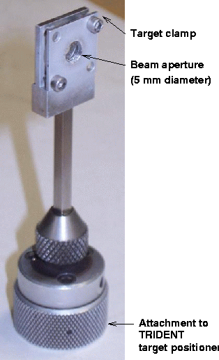
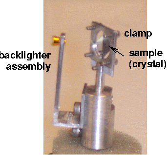
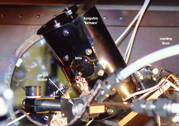
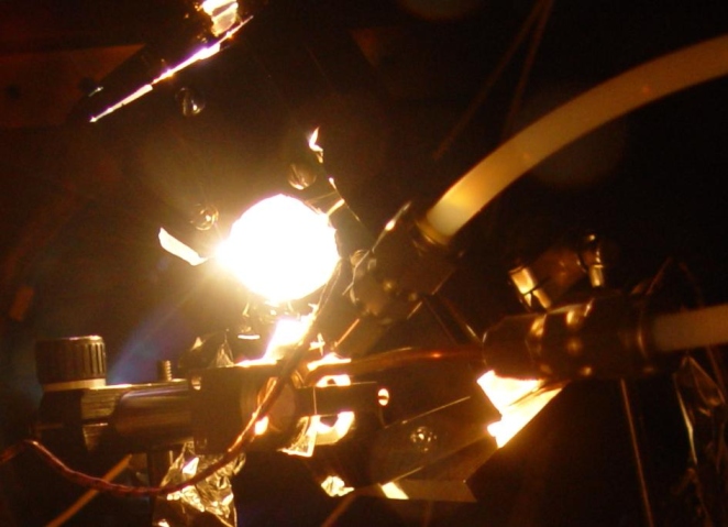
We also tried out Bryan Reed's heated and cooled holder, in which the sample was held in place by set screws. The target was in contact with a ring of Cu tubing through which coolant (water) was fed post-shot to quench the recovered sample and preserve features in the microstructure. The cooling tube was purged with nitrogen before heating. Heating was provided by a halogen lamp in a tungsten foil furnace, focused onto the target with a fast lens and mounted on a versatile bracket. Temperatures were monitored by thermocouples in the ring The cooling ring was also held in place by the force of the set screws, and target changing was awkward because of torque from the coolant tubes when working in the confined and crowded space of the chamber. The heating lamp also proved troublesome: it needed to be quite close to the sample for efficient energy coupling, but it was difficult to find a suitable position without having to remove VISAR/ellipsometry optics (not possible on this occasion), and the mounting bracket proved to be somewhat too flexible with restricted chamber access.
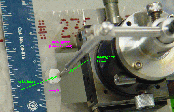
Experiments were fired with different sizes of focal spot to give different ranges of pressure in the sample. Diffractive optical elements were used where possible to smooth large-scale spatial variations in beam intensity. Generally these phase plates were not ideal for the desired uniformity or spot size, so the drive beam was defocused slightly.
| Optical settings for drive beam in target area | |||
|---|---|---|---|
| spot dia | phase plate | defocus | comments |
| (mm) | (in) | ||
| 5.0 | Fresnel zone | 0.600 | 4 mm design spot defocused to remove central hotspot |
| 1.5 | 2 mm hex | 0.339 | 0.6 mm design spot defocused for better power control and easier alignment |
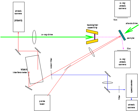
The optical layout used was based on the standard VISAR layout, with the spectrometry signal taken from the VISAR output beam path outside the vacuum chamber, making it a very convenient addition. For the first time, ellipsometry was performed simultaneously with VISAR, with incoming and outgoing beam paths to either side of the VISAR path near the target. A prototype quadrature was included, with data recorded on the camera otherwise used for ellipsometry. VISAR and TXD orientations were chosen based on early assumptions about IET experiments requiring both; in the event it was not possible to field VISAR on the IET TXD shots because of orientation constraints imposed by the wide-angle TXD holder.
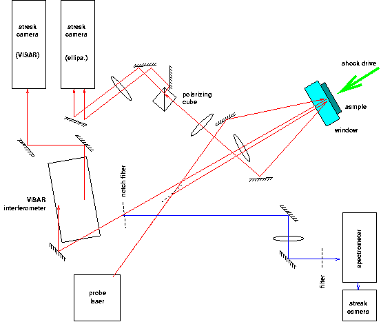
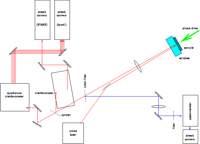
There was generally plenty of probe laser light. For NiAl shots, an OD of 2.0 was used; for Ga shots, an OD of 0.4; for polished W, an OD of 1.7.
The camera slits were set to approximately 300 µm.
An in situ alignment system was set up, comprising CCD cameras focused onto the output beamsplitter and at an equivalent focal plane of the streak camera. The pattern of speckes reflected from the sample surface could then be imaged continuously while adjusting the VISAR alignment: much more convenient then waiting for streak camera frames or juggling white cards.
The timing of the streak record relative to the drive beam was established by omitting the target and capturing light from the drive beam (in 5 Hz timing mode) down the VISAR optics to the camera. The camera delay was then adjusted until the drive pulse was visible close to the center of the record. The probe laser delay was then adjusted so the pulse appeared in the record (using a reflective target).
| VISAR streak camera delays | |
|---|---|
| sweep period | delay |
| (ns) | (ns) |
| 50 | 2825 |
| 20 | 2880 |
| 10 | 2894 |
| 5 | 2906 |
The spectrometer signal was recorded on a Hamamatsu streak camera. For a 50 ns sweep, the triggering delay necessary for the drive pulse to be at the center of the time window was 2778.5 ns.
For emission spectrometry, a grating of 100 lines/mm was used, centered on a wavelength of 700 nm and with a spectral resolution of 1.92 nm.
Some 660 nm light did propagate down the optical path for the spectroscopy. This acted as both a wavelength calibration and allowed for the possibility of Raman spectroscopy on every shot. On occasion, scatter from the 527 nm drive laser was weakly visible on the streak record.
| Ellipsometry streak camera delays | ||
|---|---|---|
| sweep period | delay | notes |
| (ns) | (ns) | |
| 50 | 2831 | A-beam at center |
| 20 | 2887 | 1st fidu pulse at center |
| 10 | 2896 | 1st fidu pulse at center |
atim1209.ipl
on the VISAR camera.
The objective of ellipsometry was to detect shock/release melting in samples of Be and Sn. A release window was necessary to maintain pressure when the shock reached the surface. LiF was chosen, as previous experience with flyer impact and isentropic compression experiments at Z had shown that it remained transparent at pressures over 200 GPa for longer times than needed in these experiments. However, it was necessary to discriminate between the effect of the LiF and the sample, so calibration experiments were performed using W samples which were expected to remain solid to shock pressures greater than for Be or Sn.
The X-ray source was helium-alpha radiation from a plasma generated with the "A" beam, focused to as small a spot as possible on a foil ~10 µm thick. Ti or Mn foils were used (wavelengths 2.61 and 2.006 Å respectively), chosen according to the lattice spacing of the sample.
X-rays from the plasma were incident on the sample material, and diffracted according to the Bragg condition. A large part of the sample was illuminated and the Bragg return occured from a circular arc in the surface.
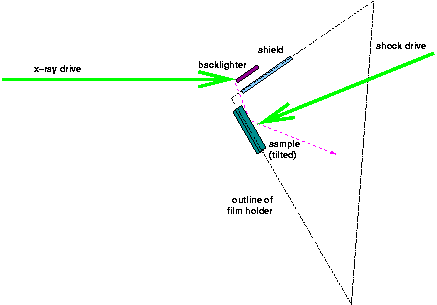
Two types of experiment were performed, with the x-ray source ~1 mm from the sample (NIF Materials IET shots) or ~15 mm from the sample (melt and NiAl LDRD shots). The x-ray source was operated at various different times with respect to the shock drive, by altering the length of a trombone. Initial timing experiments were performed in which the light from either beam (5 Hz timing signal) was directed into the VISAR optics and recorded on the streak camera. (The collecting angle of the VISAR was large enough to pick up the B - shock - beam directly by simply omitting a target.)
For the IET shots, x-rays were recorded over an octant of a sphere using two planar detectors. These comprised filtering layers and either DEF film or an image plate as the active element.
For the other shots, diffracted X-rays were recorded on Kentech X-ray streak cameras situated to the north and south sides of the target; the slit of each camera was horizontal. The sweep period of the Kentechs was set to 2.5 ns throughout. The image from the Kentech intensifiers was recorded on optical film; attempts were made to use the Retriever CCD cameras for the first time but more development work is needed. Static film packs (DEF film) were mounted in front of the slit in each camera. In some shots, a static image plate was placed vertically in front of one or other of the cameras.
The X-ray detectors were shielded from direct shine from the source by an attenuating layer. This was the standard Au truncated cone around the backlighter foil, except in the close-in IET shots where a section of a truncated cone of Pb foil was used.
The X-ray source was monitored with a spectrometer mounted with the "Tubby" film detector.
| X-ray streak camera delays | ||
|---|---|---|
| S camera | N camera | Notes |
| (ns) | (ns) | |
| 3009.1 | 3007.0 | |
Filtering comprised 125 µm Be, 37 µm Ti, the time-integrating DEF film, 10 µm Ni, and 25 µm Be, then an additional 250 µm Be in front of the S Kentech camera. From shot 16450, an additional 10 µm Ni was added in front of the film pack.
The backlighter was mounted in a half-cylinder of stainless steel ~250 µm thick acting as a shield to prevent direct exposure of the detectors by the x-rays. TRIDENT's A beam was used to generate x-rays from the backlighter, incident from the W. The beam was steered and focused with the help of a telescope viewing through the final turning mirror to the W. The alignment beam was visible even through the coated optic. The green light was focused differently from the reddish image of the target, but we reasoned that for the diffuse light visible from the backlighter foil (off-normal by some 30o, best focus was the smallest spot even when the telescope was set to focus the foil image in red. The spot size could then be verified by finding best focus in green and comparing with the (remembered) size of features in the image of the target. This procedure was reliable and fast.
For Ti backlighters and V crystal, suitable filtering was ~750 µm Be, 25 µm Ti, and 12.5 µm Cu.
Alignment was verified periodically e.g. using a sharp point, cross-hairs, or an aluminized LiF window with scratches (or ablation holes from the probe laser).
| VISAR/pyrometer/ellipsometer configuration | |||||||||||
|---|---|---|---|---|---|---|---|---|---|---|---|
| shot | target | VISAR | ellipsometer | pyrometer | drive | Comments | |||||
| sweep | delay | sweep | delay | sweep | delay | spot dia | duration | energy | |||
| (ns) | (ns) | (ns) | (ns) | (ns) | (ns) | (mm) | (ns) | (J) | |||
| 10 Dec | |||||||||||
| 16365 | W 25 and 50 µm | 50 | 2825 | 50 | 2831 | 50 | 5.0 | 2.5 | 56 | Ellipsometry: no trigger. Sample recovered. | |
| 16366 | W 25 and 50 µm | 50 | 2825 | 50 | 2831 | 50 | 5.0 | 2.5 | 49 | Ellipsometer triggered, pyrometer did not (disconnected cable). Sample recovered. | |
| 16367 | W 25 µm | 20 | 2884 | 50 | 2831 | 50 | 5.0 | 2.5 | 103 | All triggered. | |
| 16368 | W 25 µm, LiF 2000 µm | 20 | 2884 | 50 | 2831 | 50 | 5.0 | 2.5 | 103 | Excellent VISAR. Sample recovered. | |
| 16369 | W 25 µm, LiF 2000 µm | 20 | 2884 | 50 | 2831 | 50 | 5.0 | 2.5 | 169 | Sample recovered (LiF cracked). | |
| 16370 | W 25 µm, LiF 2000 µm | 20 | 2884 | 50 | 2831 | 50 | 5.0 | 2.5 | 226 | Sample recovered (LiF cracked). | |
| 16371 | W 25 µm, LiF 2000 µm | 20 | 2884 | 50 | 2831 | 50 | 5.0 | 1.7 | 244 | Sample recovered (LiF cracked). | |
| 16372 | W 25 µm, LiF 2000 µm | 20 | 2884 | 50 | 2831 | 50 | 5.0 | 1.0 | 203 | Sample recovered (LiF cracked). | |
| 10 Dec | |||||||||||
| 16375 | glass ~1 mm, Al 4 µm, Bi 125 µm | 50 | 2875 | - | - | - | - | 5.0 | 2.5 | 0.99 | Wedge for low energy. Sample flew out of holder, spattered onto blast shield. |
| 16376 | W 25 µm, LiF 2000 µm | 20 | 2884 | 50 | 2831 | 50 | 1.5 | 2.5 | 23 | Good VISAR. Pyrometry did not trigger. Sample recovered, LiF cracked. | |
| 16378 | W 25 µm, LiF 2000 µm | 20 | 2884 | 50 | 2831 | 50 | 1.5 | 2.5 | 54 | Scrappy VISAR (slightly mispointed). Pyrometry did not trigger. Sample recovered, LiF cracked. | |
| 16379 | W 25 µm, LiF 2000 µm | 20 | 2884 | 50 | 2831 | 50 | 1.5 | 2.5 | 105 | Scrappy VISAR. Pyrometry did not trigger. Sample recovered: LiF cracked. | |
| 16380 | W 25 µm, LiF 2000 µm | 20 | 2884 | 50 | 2831 | 50 | 1.5 | 2.5 | 208 | Scrappy VISAR. Pyrometry did not trigger. Sample recovered: LiF spalled. | |
| 16 Dec | |||||||||||
| 16386 | W 50 µm, LiF 2000 µm | 50 | 2835 | 50 | 2850 | 50 | 5.0 | 2.5 | 222 | Ellipsometry camera used for quadrature VISAR (1 channel). Fidus weak. | |
| 17 Dec | |||||||||||
| 16391 | MgB2 660 µm, LiF 2000 µm | 50 | 2985 | 50 | 3010 | 50 | 5.0 | 2.0 | 76 | Ellipsometry camera used for quadrature VISAR (~3 ns longer path than Forsman VISAR). Probe delay moved to 2780 ns. Shock breakout apparently earlier than start of camera frames. | |
| 18 Dec | |||||||||||
| 16395 | W 50 µm, LiF 2000 µm | 50 | 2835 | 50 | 2850 | 50 | 5.0 | 2.0 | 138 | Ellipsometry camera used for quadrature VISAR. Fidus weak. Notch filter omitted from Forsman VISAR: green light bands. | |
| 5 Jan | |||||||||||
| 16404 | W 50 µm, LiF 2000 µm | 50 | 2835 | 50 | 2850 | 50 | 1.5 | 1.0 | 150? | elements 1-6, ellipsometer not aligned, no energy reading, pyro triggering problem | |
| 16406 | W 25 µm, LiF 2000 µm | 20 | 2884 | 50 | 2831 | 50 | 1.5 | 1.0 | 150? | no energy reading, pyro triggering problem | |
| 16408 | W 50 µm, LiF 2000 µm | 20 | 2884 | 50 | 2831 | 50 | 1.5 | 1.0 | 150? | VISAR misaligned so omitted, no energy reading, pyro triggering problem | |
| 6 Jan | |||||||||||
| 16411 | W 25 µm, LiF 2000 µm | 20 | 2884 | 50 | 2831 | 50 | 1.5 | 1.0 | 150? | no energy reading, pyro triggering problem, VISAR fringes not visible after breakout | |
| 16412 | W 25 µm, LiF 2000 µm | 20 | 2884 | 50 | 2831 | 50 | 1.5 | 2.5 | 150? | no energy reading, pyro triggering problem | |
| 16413 | W 50 µm | 20 | 2884 | 50 | 2831 | 50 | 1.5 | 2.5 | 131 | poss pyrometry signal | |
| 16414 | W 25 µm, LiF 2000 µm | 20 | 2884 | 50 | 2831 | 50 | 1.5 | 2.5 | 155 | poss pyrometry signal; scrappy VISAR | |
| 16415 | Be 50 µm, LiF 2000 µm | 20 | 2884 | 50 | 2831 | 50 | 1.5 | 2.5 | 63 | probe laser on pyrometry, multi-fringe shift on VISAR, ellipsometry signal dropped a lot on breakout | |
| 16416 | Be 50 µm, LiF 2000 µm | 20 | 2884 | 50 | 2831 | 50 | 1.5 | 2.5 | 35 | Delayed pyro by 30 ns (still looked early). VISAR: ~1 fringe; ellipsometry: fluctuations after breakout. | |
| 7 Jan | |||||||||||
| 16418 | Be 50 µm, LiF 2000 µm | 20 | 2884 | 50 | 2831 | 50 | 1.5 | 2.5 | 105 | Pyro triggering was set wrong. Ellipsometry signal dropped off on breakout. | |
| 16419 | Be 50 µm, LiF 2000 µm | 20 | 2884 | 50 | 2831 | 50 | 1.5 | 2.5 | 23 | Pyro not used. Ellipsometry signal dropped off on breakout. | |
| 16420 | Be 50 µm, LiF 2000 µm | 20 | 2884 | 50 | 2831 | 50 | 1.5 | 2.5 | 36 | Ellipsometry signal dropped off on breakout. | |
| 16421 | Al 25 µm, stishovite 380 µm, Al/LiF 2000 µm | 50 | 2856 | 50 | 2862 | 50 | 1.5 | 2.0 | 167 | Probe laser delayed 30 ns to 2660 ns. Sample apparently shattered. | |
| 16422 | Be 50 µm, LiF 2000 µm | 20 | 2884 | 50 | 2831 | 50 | 5.0 | 2.5 | 105 | Ellipsometry signal dropped off on breakout. | |
| 16423 | Be 50 µm, LiF 2000 µm | 20 | 2884 | 50 | 2831 | 50 | 5.0 | 2.5 | 47 | Ellipsometry fluctuated rapidly after breakout. | |
| 16424 | Fe 30 µm, LiF 2000 µm | 20 | 2888 | 50 | 2831 | 50 | 5.0 | 2.5 | 54 | Breakout close to start of record. | |
| 16425 | Fe 30 µm, LiF 2000 µm | 20 | 2884 | 50 | 2831 | 50 | 5.0 | 2.5 | 136 | Beautiful VISAR. | |
| 8 Jan | |||||||||||
| 16427 | Fe 30 µm, LiF 1000 µm | 20 | 2884 | 50 | 2831 | 50 | 5.0 | 2.5 | 192 | Beautiful VISAR. Ellipsometry: only one line/pol visible; little effect. | |
| 16428 | Be 15 µm, LiF 2000 µm | 20 | 2884 | 50 | 2831 | 50 | 5.0 | 2.5 | 57 | Poor VISAR (breakout evident but no usable fringe shift); ellipsometry OK (no decrease on breakout). | |
| 16429 | Fe 30 µm, LiF 2000 µm | 20 | 2884 | 50 | 2831 | 50 | 5.0 | 2.5 | 239 | Good VISAR. Ellipsometry: Fe reflection was saturated on one channel; other didn't show any strong effect. | |
| 16430 | Be 30 µm, LiF 2000 µm | 20 | 2884 | 50 | 2831 | 50 | 5.0 | 2.5 | 66 | Poor VISAR (breakout evident but no usable fringe shift); ellipsometry OK (no decrease on breakout). | |
| 16431 | Sn 25 µm, LiF 2000 µm | 20 | 2884 | 50 | 2831 | 50 | 5.0 | 2.5 | 113 | Scrappy VISAR; effect on ellipsometry. | |
| 16432 | Sn 25 µm | 20 | 2884 | 50 | 2850 | 50 | 5.0 | 2.5 | 96 | Quad VISAR to ellipsometry camera. | |
| 16433 | Sn 25 µm | 20 | 2884 | 50 | 2850 | 50 | 5.0 | 2.5 | 64 | Quad VISAR to ellipsometry camera. Nice VISAR. | |
| 16434 | Sn 25 µm and 50 µm | 20 | 2884 | 50 | 2850 | 50 | 5.0 | 2.5 | 153 | Quad VISAR to ellipsometry camera. VISAR: saw one side only, contrast poor after breakout, intensity dropped off quickly. | |
| 13 Jan | |||||||||||
| 16446 | glass ~1 mm, Al 4 µm, Bi 125 µm | 50 | 2875 | 50 | 2890 | - | - | 5.0 | 2.5 | 1.07 | Wedge for low energy. Quad VISAR to ellipsometry camera. (Set up as 16445 but wrong beam was blocked in front end.) Raw 2w energy = 28 J cf 26 J previously giving 0.99 J on tgt. |
| VISAR/TXD configuration | |||||||||||||||||
|---|---|---|---|---|---|---|---|---|---|---|---|---|---|---|---|---|---|
| shot | target | Forsman VISAR | Quadrature VISAR | pyrometer | S x-ray streak | N x-ray streak | drive | backlighter | Comments | ||||||||
| sweep | delay | sweep | delay | sweep | delay | delay | delay | spot dia | duration | energy | material | angle | delay wrt drive | energy | |||
| (ns) | (ns) | (ns) | (ns) | (ns) | (ns) | (ns) | (ns) | (mm) | (ns) | (J) | (deg) | (ns) | (J) | ||||
| 12 Jan | |||||||||||||||||
| 16441 | Ga 77 µm | - | - | - | - | - | - | 3011.5 | 3009.4 | 5.0 | 2.5 | 0 | Ti | 46 | 2.4 | 168 | S TI: narrow strong lines. S TR: saturated. N: no signals. |
| 13 Jan | |||||||||||||||||
| 16443 | Ga 77 µm | - | - | - | - | - | - | 3011.5 | 3009.4 | 5.0 | 2.5 | 0 | Ti | 46 | 2.4 | 166 | S TI: narrow strong line. S TR: saturated. N: no signals. |
| 16444 | NiAl (110) 110 µm (#2) | - | - | - | - | - | - | 3011.5 | 3009.4 | 5.0 | 2.5 | 0 | Ti | 46 | 2.4 | 203 | S TI: wide strong line. S TR: saturated. N: no signals. |
| 16447 | Ga 60 µm | 20 | 2900 | 50 | 2860 | 50 | 2778.5 | 3026.6 | 3024.5 | 5.0 | 2.5 | 25 | Ti | 46 | 17.5 | 135 | Predic transit time 18.5 ns. Quad VISAR to ellipsometry camera. VISAR slightly late. S TI: couple of blotchy lines. S TR: high background, no obvious lines. |
| 16448 | NiAl (110) 94 µm (#5) | 50 | 2845 | 50 | 2860 | 50 | 2778.5 | 3026.6 | 3024.5 | 5.0 | 2.5 | 71 | Ti | 46 | 17.5 | 178 | Predic transit time 18.5 ns. Quad VISAR to ellipsometry camera. VISAR: nice elastic+plastic+release/spall. Quad VISAR: promising signal. S TI: 2 dark lines, maybe another weak line. S TR: 1-2 lines. |
| 14 Jan | |||||||||||||||||
| 16450 | NiAl (110) 102 µm (#7) | 50 | 2845 | 50 | 2860 | 50 | 2778.5 | 3026.6 | 3024.5 | 5.0 | 2.5 | 30 | Ti | 46 | 17.5 | 171 | Dot on sample down in chamber + facing backlighter. Quad VISAR to ellipsometry camera. VISAR: slight multimoding; clear elastic wave. Quad VISAR: reasonable. S TI: nothing. S TR: maybe faint signal. |
| 16451 | Ga 68 µm | 50 | 2845 | 50 | 2860 | 50 | 2778.5 | 3028.6 | 3026.5 | 5.0 | 2.5 | 48 | Ti | 46 | 19.5 | 142 | Quad VISAR to ellipsometry camera. Increased gain on S Kentech. Probe laser anti-melting block left in: no VISAR data. S TI: nothing. S TR: ~saturated. |
| 16452 | NiAl (110) 116 µm (#4) | 50 | 2845 | 50 | 2860 | 50 | 2778.5 | 3028.6 | 3026.5 | 5.0 | 2.5 | 227 | Ti | 46 | 19.5 | 124 | Dot on sample down in chamber + facing backlighter. Quad VISAR to ellipsometry camera. VISAR: drive reflections, but clear elastic, plastic, release/spall. Quad VISAR: drive reflections, no clear differentiation between channels. PCD: no x-ray signal. Tubby: no Ti line. S TI: nothing. S TR: almost saturated (suspect intensifier problem). |
| 16453 | Ga 66 µm | 50 | 2845 | 50 | 2860 | 50 | 2778.5 | 3028.6 | 3026.5 | 5.0 | 2.5 | 58 | Ti | 46 | 19.5 | 156 | Quad VISAR to ellipsometry camera. Switched N and S Kentech intensifiers. VISAR: lots of drive reflections, but noisy elastic + plastic waves. S TI: broad lines. S TR: broad lines (may be photocathode noise). |
| 16454 | NiAl (111) 114 µm (NiAl-111-04-3) | 50 | 2845 | 50 | 2860 | 50 | 2778.5 | 3028.6 | 3026.5 | 5.0 | 2.5 | 231 | Mn (?) | 53 | 19.5 | 98 | Dot on sample down in chamber + facing backlighter. Quad VISAR to ellipsometry camera. Probe laser: slight multi-moding. VISAR: drive reflections; clear elastic wave, low amplitude plastic. Quad VISAR: many reflections; possibly usable fringe data (noisy). S TI: nothing. S TR: broad lines (may be photocathode noise). |
| 15 Jan | |||||||||||||||||
| 16456 | Ga 66 µm | 50 | 2845? | 50 | 2860? | 50 | 2778.5? | 3028.6 | 3022.0? | 5.0 | 2.5 | 62 | Ti | 44 | 17.4 | 165 | Filtering: removed 25 µm Ti to leave to 6 mil Be, 12.7 µm Ti, 10 mil Be. |
| 16457 | Ga 67 µm | 50 | 2845? | 50 | 2860? | 50 | 2778.5? | 3028.6 | 3022.0? | 5.0 | 2.5 | 26 | Ti | 44 | 17.4 | 170 | |
| 16458 | NiAl (111) 82 µm (NiAl-111-04-4) | 50 | 2845 | 50 | 2860 | 50 | 2778.5 | 3024.1 | 3022.0 | 5.0 | 2.5 | 101 | Mn | 53 | 15 | 243 | |
| 16459 | NiAl (111) 88 µm (NiAl-111-04-7) | 50 | 2845 | 50 | 2860 | 50 | 2778.5 | 3025.1 | - | 5.0 | 2.5 | 211 | Mn | 53 | 15 | 228 | Great VISAR record. TXD nearly identical to previous shot... photocathode noise? |
| 16460 | NiAl (111) 88 µm (NiAl-111-04-11) | 50 | 2845 | 50 | 2860 | 50 | 2778.5 | 3025.1 | - | 5.0 | 2.5 | 134 | Ti | 38 | 15 | 121 | TXD shows pc noise, but has visible line that is different from Mn backlighter shots. |
| 16 Jan | |||||||||||||||||
| 16462 | Ga 68 µm | 50 | 2845 | 50 | 2860 | 50 | 2778.5 | 3028.6 | - | 5.0 | 2.5 | 95 | Ti | 46 | 19.5 | 130 | Probe laser flaky... failed to produce pulse on this shot. |
| 16463 | NiAl (111) 98 µm (NiAl-111-04-5) | 50 | 2845 | 50 | 2860 | 50 | 2778.5 | 3026.6 | - | 5.0 | 2.5 | 233 | Ti | 38.5 | 17.5 | 132 | Special Request shot by Aaron Koskelo. Great VISAR record, similar to shot 16459 with pull-back visible at e-p transition. Interesting Pyrometer signal--- Raman candidate? |
| 16464 | Ga 59 µm | 50 | 2845 | 50 | 2860 | 50 | 2778.5 | 3026.6 | - | 5.0 | 2.5 | 147 | Ti | 46 | 17.5 | 152 | PC noise, TI TXD decent. |
| 16465 | NiAl (111) 100 µm (GE) | 50 | 2845 | 50 | 2860 | 50 | 2778.5 | 3027.6 | - | 5.0 | 2.5 | 221 | Ti | 38 | 18.5 | 125 | Great VISAR. TI TXD good, some interesting lines on TR TXD. |
| Wide-angle TXD configuration | ||||||||||
|---|---|---|---|---|---|---|---|---|---|---|
| shot | target | backlighter | A (backlighter) beam | B (drive) beam | tA-tB | Comments | ||||
| spot dia | duration | energy | spot dia | duration | energy | (ns) | ||||
| (mm) | (ns) | (J) | (mm) | (ns) | (J) | |||||
| 15 Dec | ||||||||||
| 16381 | Ti (0001) 40 µm | Ti 7 µm | ~0.1 | 2.0 | 246 | 5.0 | 2.0 | 0 | 4.2 | Film saturated, IPs probably saturated, probably hit steel shield. |
| 16 Dec | ||||||||||
| 16383 | Si (111) 380 µm | Ti 7 µm | ~0.1 | 2.0 | 119 | 5.0 | 2.0 | 0 | 4.2 | No signals (film behind IP). |
| 16384 | Si (111) 380 µm | Ti 7 µm | ~0.1 | 2.0 | 186 | 5.0 | 2.0 | 0 | 4.2 | Broad line on film. |
| 16385 | Al/CH 5 µm, V (110) ~2000 µm | Ti 7 µm | ~0.1 | 2.0 | 195 | 5.0 | 2.0 | 0 | 4.2 | Line on film, quite high background. |
| 17 Dec | ||||||||||
| 16388 | Al/CH 5 µm, V (110) ~2000 µm | Ti 7 µm | ~0.1 | 2.0 | 122 | 5.0 | 2.0 | 39 | 0.75 | Broad line on film, PCD signal finally. |
| 16389 | Al/CH 5 µm, V (110) ~2000 µm | Ti 7 µm | ~0.1 | 2.0 | 147 | 5.0 | 2.0 | 88 | 0.75 | Lines on both films. |
| 16390 | Al/CH 5 µm, V (110) ~2000 µm | Ti 7 µm | ~0.1 | 2.0 | 128 | 5.0 | 2.0 | 138 | 0.75 | Weak lines. |
| 16392 | Al/CH 5 µm, V (110) ~2000 µm | Ti 7 µm | ~0.1 | 2.0 | 146 | 5.0 | 2.0 | 0 | 0.75 | Fairly weak lines, quite broad - sample surface (rough)? |
| 16393 | Al/CH 19 µm, Ti (0002) 40 µm | Ti 7 µm | ~0.1 | 2.0 | 157 | 5.0 | 2.0 | 0 | 0.75 | Strong lines, quite broad, triplet evident. |
| 18 Dec | ||||||||||
| 16396 | Al/CH 19 µm, Ti (0002) 40 µm | Ti 7 µm | ~0.1 | 2.0 | 154 | 5.0 | 2.0 | 15 | 2.4 | X-ray filtering changed to 50 µm Ti. |
| 16397 | Al/CH 19 µm, Ti (0002) 40 µm | Ti 7 µm | ~0.1 | 2.0 | 126 | 5.0 | 2.0 | 21 | 2.4 | ST-V IPs in 25 µm Al around chamber: no signal recorded but PCD and film good (shocked line weak/blurred) so maybe problem with scanner. |
| 16398 | Al/CH 19 µm, Ti (0002) 40 µm | Ti 7 µm | ~0.1 | 2.0 | 126 | 5.0 | 2.0 | 72 | 2.55 | Moved other end of A trombone by 0.75". Various lines. |
| 16399 | Al/CH 19 µm, Ti (0002) 40 µm | Ti 7 µm | ~0.1 | 2.0 | 135 | 5.0 | 2.0 | 70 | 2.55 | Moved other end of A trombone by 0.75". Various lines. |
| 16400 | Al/CH 19 µm, Ti (0002) 40 µm | Ti 7 µm | ~0.1 | 2.0 | 136 | 5.0 | 2.0 | 79 | 2.4 | Moved other end of A trombone back 0.75". Apparently unshocked lines but not shocked. |
| 16401 | Al/CH 19 µm, Ti (0002) 40 µm | Ti 7 µm | ~0.1 | 2.0 | 140 | 5.0 | 2.0 | 72 | 2.4 | Shocked and unshocked lines, including previously unseen ones. |
Ellipsometry reference data were successfully obtained for W through an LiF release window, to max energy at ~1.5 mm diameter. Be data were collected, but the ellipsometry signals showed a huge effect from relatively low drive pressures. It is therefore not clear whether ellipsometry will be suitable for detecting melt in Be specifically. High-resolution ellipsometry may make these measurements possible, but this should be regarded as high risk.
Wide-angle TXD data were obtained on crystals of Ti and V. The Ti showed clear line motion and apparently the appearance of new lines.
Beautiful VISAR records were obtained showing the elastic precursor and plastic wave in (110) and (111) crystals, also comparing GE and LANL material. TXD signals were obtained (moving lines). No samples were recovered because of conflict with TXD and VISAR diagnostics: the samples did not remain in the TXD target holder.
The emission spectrometry diagnostic was successfully fielded simultaneously with line VISAR and ellipsometry. Problems were encountered with the camera control software; once these were solved spectra were obtained. It is too early to say whether spectra included surface emission or just plasma light. There was also evidence of Raman-like lines.
Some TXD development was performed as part of the NIF Materials IET studies.
Some Ga TXD shots were fired, but preshot Laue patterns were delayed by IWD-related issues in MST (these were to be obtained as a favor rather than through formal funding, so the work was performed at best effort). There may be useful data from the TXD records. Additional Sn VISAR/ellipsometry data were obtained, to calibrate the drive at higher pressures corresponding to melt on release.
Secondary objectives:
Quadrature signals were obtained; analysis will show whether these are usable data or whether more development is needed. The Forsman line VISAR was used simultaneously, so reference velocity histories are available.
Cancelled because of a lack of time - effort devoted to solving problems with pyrometry camera.
The LLNL preheater was tested on one (almost two) shots. Various problems were encountered, but this was valuable experience for future experiments.
Cancelled as per C beam x-ray yields.
The Retriever CCD cameras were fielded on the Kentech streak units. The triggering system on the Retriever cameras seemed to work incorrectly: manual triggering from outside the target room was used successfully.
| Pedro Peralta, Ken McClellan, Darren Byler, John Brooks | NiAl sample preparation and characterization. |
| Randy Johnson | Laser/optics consulting |
| David Montgomery | Suggestions about phase plate usage for small drive spots. |
| Tom Hurry, Nathan Okamoto, Tom Ortiz, Ray Gonzales, Fred Archuleta | target area and laser work |
| Joe Cowan | photographic support |
| Tom Sedillo | engineering support for hot/cold stage |
| Allan Hauer | Project support (use of TRIDENT) - C10: HEDP |
| Scott Bardenhagen | bard@lanl.gov
|
| Cris Barnes | cbarnes@lanl.gov
|
| Steve Batha | sbatha@lanl.gov
|
| John Brooks | jdbrooks@lanl.gov
|
| Darren Byler | dbyler@lanl.gov
|
| Jim Cobble | cobble@lanl.gov
|
| Robert Gibson | rbg@lanl.gov
|
| Scott Greenfield | greenfield@lanl.gov
|
| Doran Greening | dgreening@lanl.gov
|
| Allan Hauer | hauer@lanl.gov
|
| Nelson Hoffman | nmh@lanl.gov
|
| Randy Johnson | rpjohnson@lanl.gov
|
| Aaron Koskelo | koskelo@lanl.gov
|
| George Kyrala | kyrala@lanl.gov
|
| Shengnian Luo | sluo@lanl.gov
|
| Ken McClellan | kmcclellan@lanl.gov
|
| Carter Munson | cmunson@lanl.gov
|
| Dennis Paisley | paisley@lanl.gov
|
| Mike Sorem | msorem@lanl.gov
|
| Damian Swift | dswift@lanl.gov
|
| Tom Tierney | tierney@lanl.gov
|
| External: | |
|---|---|
| Eric Loomis (ASU) | |
| Pedro Peralta (ASU) | |
| Hector Lorenzana (LLNL) | |
| Bruce Remington (LLNL) | |
| Jeff Colvin (LLNL) | |
| Bryan Reed (LLNL) | |
